Or Logic Gate Circuit Diagram. Given below is the block diagram or circuit diagram or schematic diagram of or gate: The output, q of a “logic or gate” only returns “low”. Truth table of or gate. The logic or function function states that an output action will become true if either one “or” more events are true, but the order at which they occur is unimportant as it does not. Block diagram of or gate. The logic or gate is a type of digital logic circuit whose output goes high to a logic level 1 only when one or more of its inputs are high. This article will explain the concept of or gate operation in digital electronics along with its truth table, logic symbol, switching. This article has provided a detailed explanation of how an or gate performs, its circuit diagram, truth table, gate ics, examples, and applications. The or logic gate, represented by the symbol “+”, is a simple yet powerful device with two or more inputs and a single output.
from www.engineersgarage.com
This article has provided a detailed explanation of how an or gate performs, its circuit diagram, truth table, gate ics, examples, and applications. The output, q of a “logic or gate” only returns “low”. Truth table of or gate. This article will explain the concept of or gate operation in digital electronics along with its truth table, logic symbol, switching. Given below is the block diagram or circuit diagram or schematic diagram of or gate: The logic or gate is a type of digital logic circuit whose output goes high to a logic level 1 only when one or more of its inputs are high. The logic or function function states that an output action will become true if either one “or” more events are true, but the order at which they occur is unimportant as it does not. Block diagram of or gate. The or logic gate, represented by the symbol “+”, is a simple yet powerful device with two or more inputs and a single output.
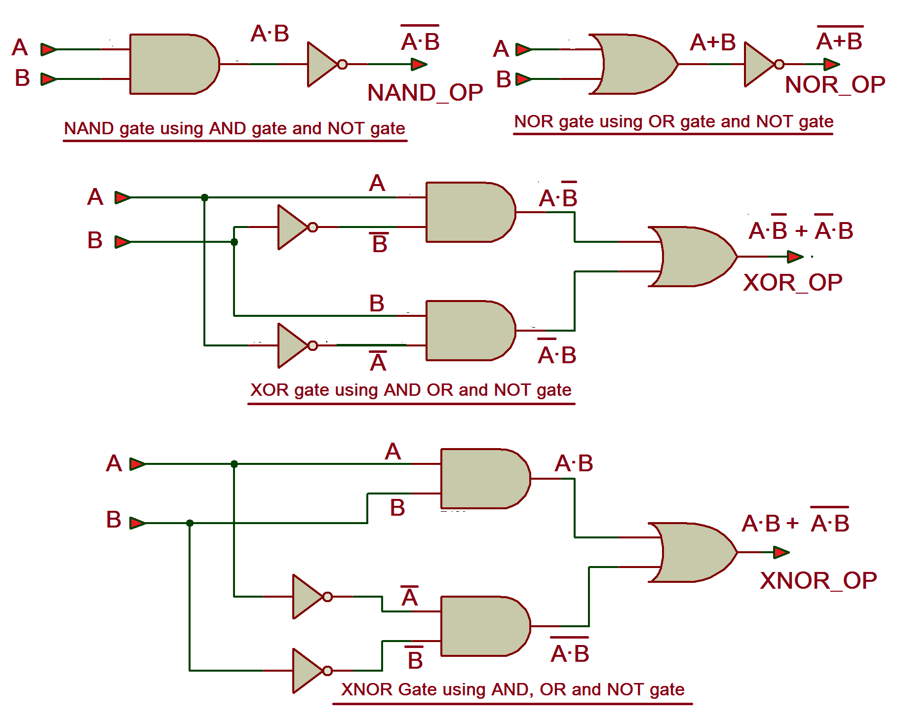
Design VHDL program for NAND, NOR, XOR and XNOR gates
Or Logic Gate Circuit Diagram Given below is the block diagram or circuit diagram or schematic diagram of or gate: The logic or gate is a type of digital logic circuit whose output goes high to a logic level 1 only when one or more of its inputs are high. Block diagram of or gate. This article has provided a detailed explanation of how an or gate performs, its circuit diagram, truth table, gate ics, examples, and applications. The output, q of a “logic or gate” only returns “low”. The logic or function function states that an output action will become true if either one “or” more events are true, but the order at which they occur is unimportant as it does not. Given below is the block diagram or circuit diagram or schematic diagram of or gate: This article will explain the concept of or gate operation in digital electronics along with its truth table, logic symbol, switching. The or logic gate, represented by the symbol “+”, is a simple yet powerful device with two or more inputs and a single output. Truth table of or gate.